PicoArcade Part 1: Hardware
This is part 1 of a series on the PicoArcade project. Check out the main page to see the full series.
Objective
The point of this endeavour was to build a small but versatile arcade system with the following functions:
- 16 led-lit buttons, all programmable
- A screen to display game modes, score, etc…
- Simple audio alerts
- It should run without being plugged in
To get acquainted with the Raspberri Pi Pico (called simply Pico in the following), I bought a starter kit from Sunfounder. I went through most of their projects which I found pretty well made and explained for the most part.
And with that, I felt confident enough to start designing my system, going back and forth between the electrical design and the components I could find online.
Box


The box is the only thing I outsourced in this project. My father-in-law is very handy, and he built a box by soldering some PVC panels together (during which I learned how PVC could be soldered), and gluing a sheet of aluminum on it. Once all the holes were done, he gave it a good polish, and the whole thing came out quite nice! It’s a bit on the heavy side, but after all that’s good, people might be smashing the buttons on this at some point, I like it sturdy.
Inside, I attached everything to the underside of the top plate, as you can see in the open box right below.
Internal layout

The internal layout is mapped out more precisely on this underside picture. You can see:
- The button rows, made up of two groups of 8: blue / white (group 1) and red / yellow (group 2).
- Each group is controlled (both to monitor button clicks and to set LED values) by a dedicated multiplexer at the top.
- The heart of the system, the Raspberry Pi Pico microcontroller, sits between the multiplexers (magenta).
- Another group of switches sits at the top right (green), with 5 buttons in a cross shape.
- At the center top sits the OLED screen (blue).
- To its right is the buzzer (orange).
The system has 2 outgoing USB cables:
- A power-only USB cable (blue), routed through a rotary switch (teal). This connects to a standard power bank, kept inside the box. It is hooked to the Pico power pin.
- A power + data USB cable (yellow), connected to the micro-USB port of the Pico, used to connect to the computer and upload files.
Let’s dive deeper into the details of each component.
Button hardware
Buttons are supposed to be the stars of the show here. I looked for some sturdy, led-lit buttons, with no rim around the actual button so that they could be smashed easily. I found these great 24mm ones at the PiHut. I got them in 4 colors, to add a bit of diversity.
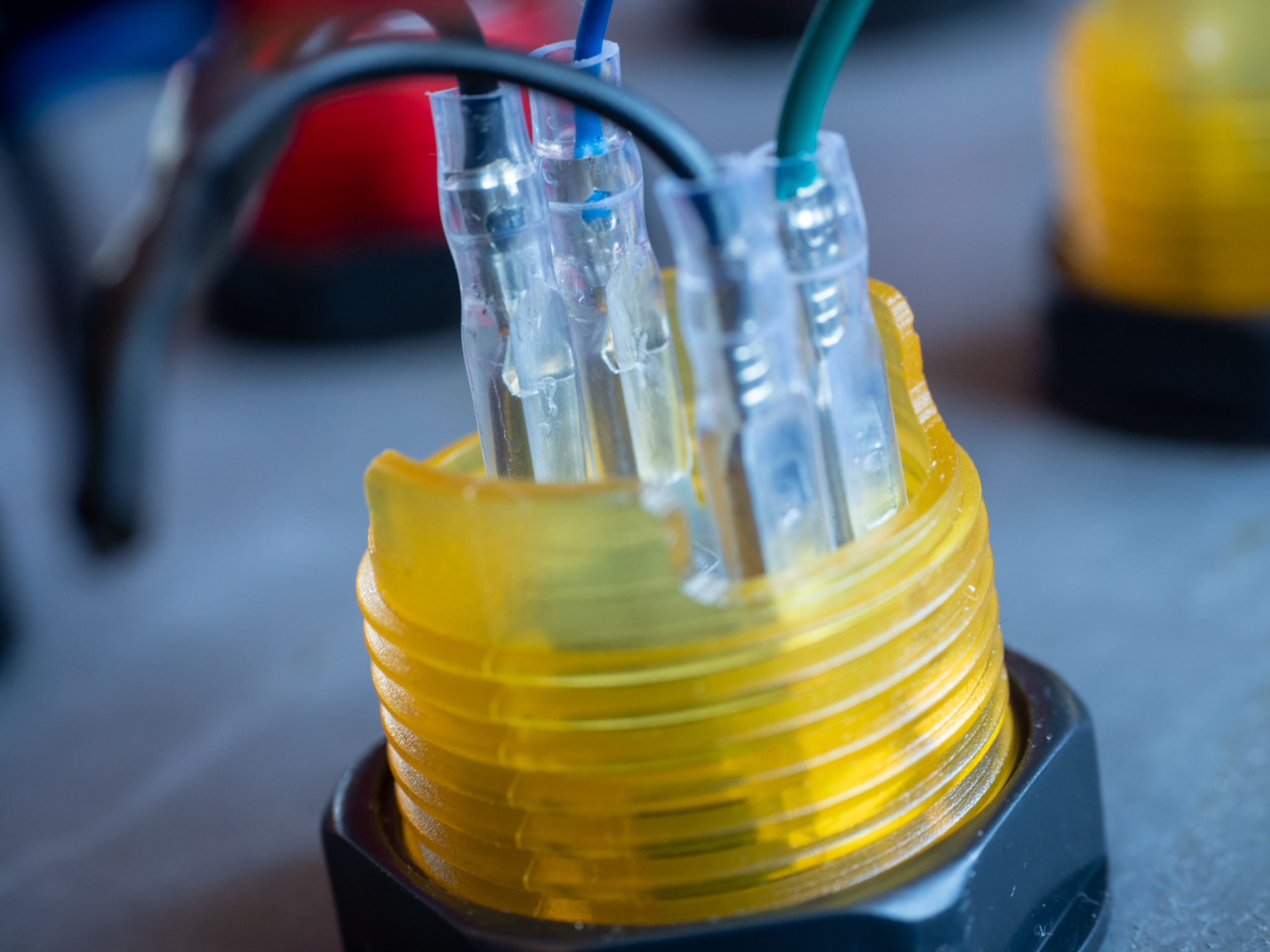
They use spade quick-connectors, which I needed quite a lot of… 16 buttons means as many independent wires to detect if each is pressed or not, and the same goes for the LEDs. Plus of course all the commons. That’s already too much for the Pico, which only has 28 programmable GPIO pins (General Purpose Input/Output). Now, I did realize that one way of getting out of this was by multiplexing the LEDs and buttons.
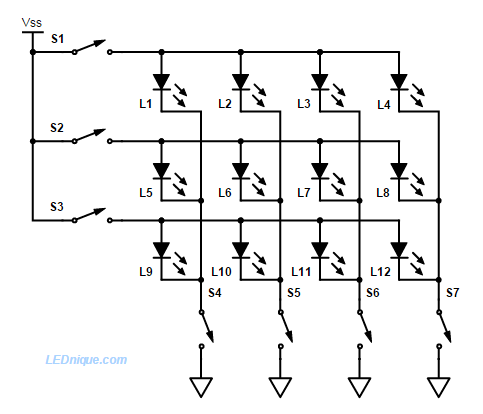
This would only require 8 GPIOs: 4 for rows, 4 for columns. It would however still take away 16 of my GPIO pins for this, but more importantly, it would have been quite a hassle on the software side. Indeed, you need to continually loop over e.g. the lines, and for each light up the right LEDs (and detect the pressed buttons) by looping over columns. When this is done fast enough, retinal persistence is sufficient to not notice the flickering of the LEDs.
But then, I ran across some neat cheap boards that could make my life a lot easier: Adafruit’s AW9523, and Waveshare’s MCP23017 IO expansion board. I got both, for good measure… but in the end, I went with Waveshare’s version because I couldn’t get find simple micropython drivers for Adafruit’s ones (see the next post for details).
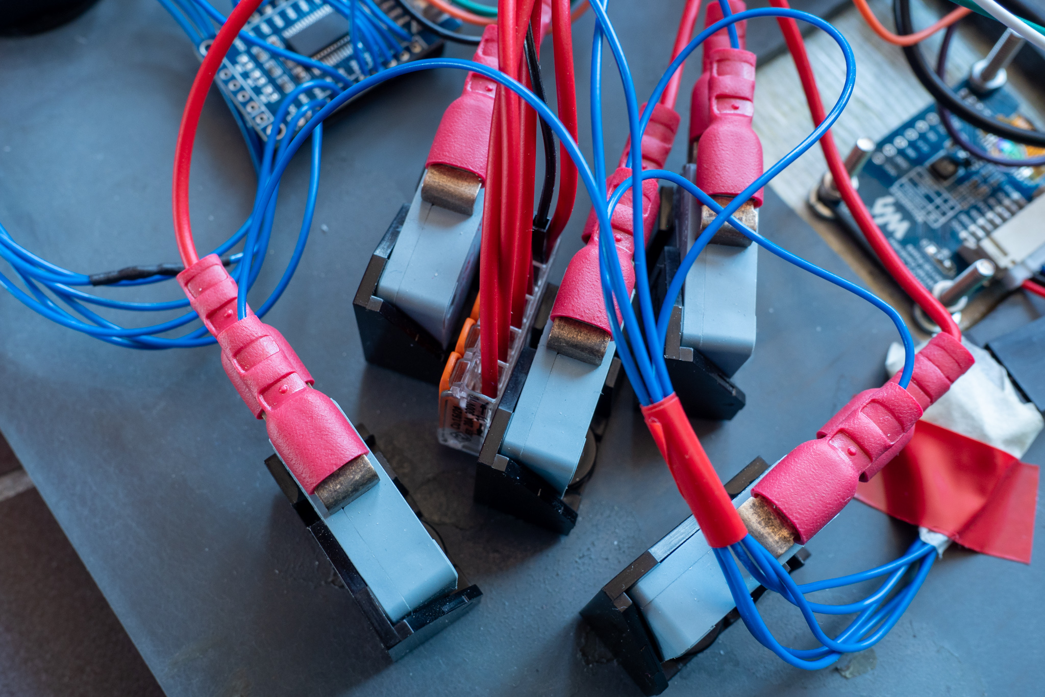
Finally, there is another set of buttons for the top control panel. For these, my box-builder had some standard switches lying around. Notice that I used a Wago connector for the commons (unfortunately in red wires here, I didn’t have black when I did them).
Screen
I didn’t need any color for the screen, so I simply went with a 64x128 B&W OLED screen by Waveshare. I ended up having a lot of trouble with it, and as of now it still doesn’t work. I hope I can get back to it at some point.
USB shenanigans
I wanted to be able to switch easily between two power sources:
- an internal battery, that enables the system to run without being plugged in
- a usb connection to a computer, which includes data.
The first thing to know is that the Pico runs on 3.3 V internally. USB however provides 5V, so a step-down (and better yet, a voltage regulator) is needed. I had to dig a little bit into the schematics of the power system of the Pico to see how that worked. Check it out:


This shows several things:
- The VBUS pin (n°40) is actually directly connected to the USB 5V input.
- The VSYS (n°39) pin should also have a tension of 5V, as it is connected through a simple diode to VBUS.
- However, and very importantly, no current can flow from VSYS to the USB, thanks to the diode. This is not true of VBUS, which is directly connected to the USB power.
- All of this does indeed feed into a voltage regulator that’s in charge of keeping the Pico voltage at 3.3 V.
- The 3V3_EN pin (n° 37) is pulled high to VSYS via a 100K resistor. Its purpose is to be shorted in order to depower the Pico, according to the datasheet. Not needed in our case.
- Pin 3V3 (n°36) is the regulated voltage output used by the Pico to run, and to which we can also hook up external systems. The total load on this pin should not exceed 300 mA, according to the datasheet.
So, with all that in place, I realized that to connect 2 power sources, I might be putting my computer in danger if I were to connect it to the USB port, and simultaneously power the VBUS port with another battery. And so I decided to connect the power bank to the VSYS pin.
Conclusion
I skipped a lot of the small things I learned along the way in the assembly process. I was e.g. very happy when I figured out that I could easily assemble Dupont connectors myself, after buying a nice little kit like this one:

My second multiplexer (on the right) was much cleaner than the horrible job I did with the first one (on the left), with no connectors.


That’s all for this part. The next post goes over the software aspects (and mistakes…) of the project.